User:Yiming/Proposal 2018/UserDocument/Modes/Software
< User:Yiming | Proposal 2018 | UserDocument | Modes
Basic Usage
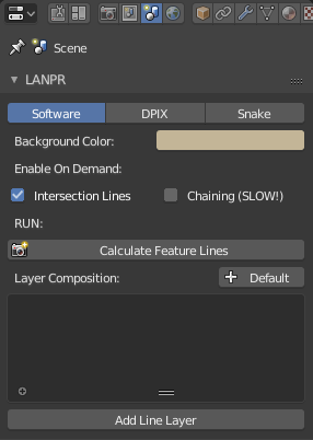
When you first switched to LANPR Software mode, there will be blank in your viewport render-preview. That is because the line calculation haven't been done yet. If you want the line rendering result, just click the "Calculate Feature Lines" button, it will trigger the software calculation.
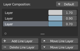
After calculation, you need at least one layer to draw the lines. Click "Add Line Layer" will add one line layer. Or you can choose to create a default present using "+ Default" button.
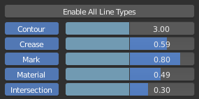
Once you have at least one layer, you can then enable or disable different line types. Adjust the color and thickness of each line type.
You be able to see the preview result in your viewport now.
The thickness of crease, edge mark, material, intersection lines is relative to contour line's thickness. So once you adjust the thickness of contour, you adjust the entire layer's absolute line thickness.
You can also quick adjust contour color and thickness in the line layer list.
Rendering Output
Hit F12 will trigger the actual render. If you already executed "Calculate Feature Lines" for this frame, then the render will simply draw the result onto the image. If you haven't, then the render will first do the calculation, then it will draw the results. Animation render will re-calculate lines for each frame.
note: If you accidentally changed frame, don't worry, just skip back to the calculated frame, and your result is still there. If you changed the frame and calculated the feature lines again, then the calculation result of the original frame is no longer available.
More Features
Visibility
Line visibility level is also adjustable. You can select "Visible", "Invisible" or manually set QI Range for your usage. The default line layer present uses a three layer config, each layer includes a QI Range of 0,1,2, which represent the line segments who are occluded one/two/three times by other faces.
Line Selection
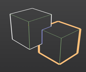
Select lines from specific objects/collections/materials is available (if chaining is not enabled). If you see the "Including" subpanel in LANPR, you can add line selection from there.
If you add one object, then LANPR will draw this line layer with lines that only belongs to this specific object. The same is true for Collection and Material.
If you add multiple elements, LANPR will draw them all. (As the OR-logic in Freestyle's) Click the minus button on the right side to delete an element.
If there's no selection, LANPR will draw everything in the scene. But if add a selection of "all" to one layer, LANPR will select every single line that haven't been drawn by other layers.
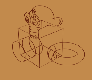
The image on the right shows the line selection in operation. The yellow lines are selected from specific object. then, an "all" selection is used to draw the other lines.
note: Line layers are drawn from bottom to top.
Intersection Calculation
You can enable or disable the intersection calculation. If disabled, Intersection line type will not be available. But enable intersection will increase calculation time.
Intersection lines are calculated in view field, geometries that are out of view region is ignored. So the calculation time depends on how many things you can see in camera viewport.
Chaining
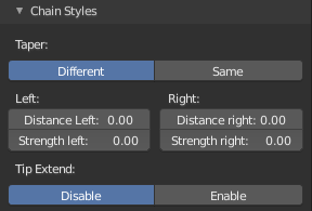
You can enable or disable line chaining. If enabled, you can adjust 1D line styles on the "Chain Styles" below. But currently LANPR can not select lines from specific objects or collections when you enabled chaining. The image on the right shows the chaining effect without occlusion.
note: If you just want thin and solid lines, then you don't need chaining, because tiny gaps are not visible in thin lines, and solid line means no style is needed along the curve.
Few more things
- Don't use Edge Split modifier! That thing is stupid... use edge mark and auto smooth instead!
- Don't have completely coincident faces in your mesh. This is very likely due to a modeling error.
- Remove Doubles before calculation is recommended.
