Source/Nodes/Modifier Nodes
Modifier Nodes
Geometry Nodes Modifier
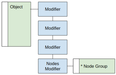
The "Geometry Nodes Modifier", or "Nodes Modifier" for short, is a a modifier to handle more complex behavior. Its logic is built with a node group owned by the modifier. The geometry node group which can be used by multiple modifiers on different objects, or shared for different projects, just like a shader node group. High level settings are exposed in the modifier stack.
Any of the existent modifiers can be ported to nodes, though they may need small adjustments in a per-case basis.
Geometry Node Editor
The modifier's node group is edited in the node editor. The editor is context sensitive, showing the modifier node group of the active modifier of the active object.
High Level Abstraction
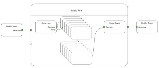
Modifiers are black boxes with geometry as the main input and output. External dependencies are possible on ID level. Users should be able to use the system in a high level. More general nodes contain several lower level building block nodes, with certain parameters exposed.
The building blocks of the system are kept inside the main node groups, abstracted away but tweak-able for advanced usage. Properties connected to the node group input are exposed in the modifier stack.
Inputs and Outputs
The modifier input and output are explicit nodes that represent the flow of geometry into and out of the modifier. The modifier must have a geometry output
Data Flow
The high level nodes operate with a clear flow of data. This means that each node finishes its calculation independently, then passes the resulting data to its output nodes.
Geometry Sockets
The geometry socket is used to pass around multiple types of data
- Meshes
- Point cloud
- Instances data
- Hair
- Volume
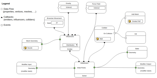
Those data types, as well as the mesh objects can be passed around in the nodetree via the "Geometry" socket. It is possible for the system to handle implicit conversion, but there are explicit settings required in some cases. Often, the simulation effects require a different input and output geometry types. For example, in this image a spray node gets the nozzle as input, and outputs foam particles. (The icons represent the data type output.)
Different Socket Types for Geometry Types?
One question that comes up a lot is why one socket is used for all geometry data types, instead of a separate for each socket type. There are arguments in both directions, but in general a single socket makes much more sense.
Pro Multiple Socket Types
- One knows exactly what geometry type one is working with at any point.
- Transformation of one data type to another is displayed visually.
Pro Single Socket Type
- Requires fewer socket types (otherwise we might need socket types for mesh, volume, curve, text, metaballs, point clouds, hair, grease pencil).
- Some nodes can work on multiple different geometry types (e.g. Transform). Those would have to exist multiple times or have some kind of dynamic input.
- The geometry node group used by a modifier can have exactly one output, no need for one output per type.
- When building a node group that displaces points, one probably does not care whether the points belong to a mesh, curve, hair or whatever. The group could have a point cloud input, but then all the connectivity data would be lost after the displacement.
- Most other node-based software uses a single socket type for this purpose.
- A common workflow is to first build smaller objects of various types, which are then joined into bigger objects and so on. These bigger objects are mostly only transformed and instanced. At that point there is no need to distinguish between different geometry types anymore. You wouldn't want to copy Transform nodes multiple times to transform all components the same way. A single Transform node in the node tree should be enough.
More Thoughts
Some of the disadvantages of having multiple socket types can be counteracted by introducing yet another "generic geometry" socket type that can be anything and can be used on nodes that support multiple types. But there is more complexity to deal with: What if a node only supports a subset of all geometry types (e.g. shrinkwrap), do we use a different type for the different combinations? Also, how does instancing fit into the design when there are multiple socket types? Is there a separate "Instances" socket? What happens if you want to make those instances "real"? The type of the instances might not be known statically, and might change over time.
So on balance, it's better to use a single socket type, and make it clear in the documentation and UI which data types each node supports.
Attributes
An important part of the pipeline is to assign attributes to the geometry to change how the geometry looks and behaves.
Attribute Names
See the manual for a list of built-in attributes and further description of attribute types: https://docs.blender.org/manual/en/latest/modeling/geometry_nodes/attributes_reference.html
Data Types
The user manual has more information about data types: https://docs.blender.org/manual/en/latest/modeling/geometry_nodes/attributes_reference.html#attribute-data-types
In the code, attributes are generally stored with the basic types: bool, int, float, float2, float3, ColorGeometry4f.
However, attribute providers can also give access to attributes embedded in other structs.
Implicit conversions between data types are defined in create_implicit_conversions in BKE_type_conversions.hh.
Naming
Built-in and name convention attributes use "snake_case", while user defined attributes are initialized as "PascalCase", but can be renamed later to anything (Unicode characters, spaces, lowercase characters, etc.).
Abbreviation
For all types of attribute names, abbreviations are to be avoided. If they eventually happen, they should be lower case for the built-in attributes. For user defined attributes they can be decided on a per-case basis.
Instances
The user manual has more information about geometry nodes instancing: https://docs.blender.org/manual/en/latest/modeling/geometry_nodes/instances.html
There are many ways to create instances in Blender:
- Collection instances
- Child instancing (The "Instances" panel in the property editor)
- Instances created by the "Instance on Points" node.
- The "Object Info" and "Collection Info" nodes can output instances instead of copied geometry.
Geometry nodes treats instances as a first class type, with their own attributes. Instances must be realized explicitly with the realize instances node.
Event-Based Simulation Concept
Many simulations can be implemented with existing geometry nodes. However, a more complex setup could be considered in the future. The design in this section hasn't been validated since it was last discussed in 2020, however many sections may still apply. For events there is a need for a different representation for its callbacks.
Conversion vs Emission
- Conversion tries to convert from different data types close to 1:1
- Emission requires distribution functions + maps
Simulation Context
The simulation context is defined by the current view layer. If the simulation needs to be instanced in a different scene it has to be baked to preserve its original context.
Baking vs Caching
- Baking overrides the modifier evaluation (has no dependencies)
- Caching happens dynamically for playback performance
Interaction and physics
- Physics needs its own clock, detached from animation playback
- There is no concept of (absolute) “frames” inside a simulation
Solver Node
The solver node requires new kind of input, the influences.
The geometry is passed to the solver as the initial points (for the particles solver). The solver reaches out to its influences that can:
- Create or delete geometry
- Update settings (e.g., color)
- Execute operations on events such as on collision, on birth, on death.
In this example the callbacks are represented as vertical lines, while the geometry dataflow is horizontal.
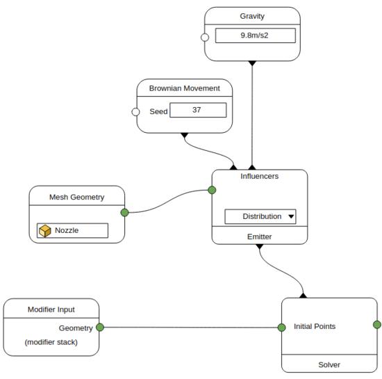
Emitter Node
The emitter node generates geometry in the simulation. It can receive its own set of influences that will operate locally. For instance, an artist can setup gravity to only affect a sub-set of particles.


